Mounting of membrane switches and nameplates
On the rear side, membrane switches and nameplates are provided with an adhesive layer, protected during transport and storing with silicone paper, or a film liner. A customer can bond the membrane switch (nameplate) to the control panel himself, or he can order supplies of membrane switches (nameplates) mounted to the panel which he provides, or which he orders at the membrane switch & nameplate manufacturer.
Current panels are usually of aluminium alloys, or fibreglass. We can outfit the panel with cut-outs or studs (standoffs) with a male/female thread for mounting. The studs are clinched in the panel and are safe against pulling out and turning.
The quality of the bond between the membrane switch (nameplate) and the panel, primarily its life-span, the appearance of the assembly, but also its correct functioning, depend on the surface of the panel on which the membrane switch (nameplate) will be bonded, the adhesive type, and on the mounting procedure. Before you order a membrane switch or nameplate, consult the switch (nameplate) manufacturer on the surface to which the product will be bonded, for a selection of the right type of adhesive.
Convenient panel surface
plane, smooth, rigid (no sag), degreased, removed gate residues and flashes
Inconvenient panel surface
greasy, uneven, flexible, unseasoned paint, unseasoned plastic, gate residues, flashes etc.
Panel surface preparation
Use isopropanol or heptane to clean and degrease the substrate (do not use denaturated alcohol and petroleum as they leave a greasy film)
Panel material
1. The surface to which you want to bond the membrane switch (nameplate) must have a surface energy high enough (e.g. polyamide, silicone etc. have too low surface energy). For low surface energy materials there are special adhesives - please consult manufacturer.
2. The coefficient of contraction of the panel must correspond to the contraction of the membrane switch (nameplate) films, which is 16·10-6 cm/cm·°C (if the contractions of the panel and the membrane switch differ too much, short circuits will occur up and the films can separate when the temperature changes)
Recommended procedure for installing the membrane switches
1. Peel off the protective liner in the tail area
2. Pass the tail through a cut-out in the panel
3. Align the membrane switch properly
4. Progressively peel the protective liner off and slowly bond the membrane switch with it moderately bent back, and with a rolling motion (bond it carefully)
5. On bonding, you are especially reminded that dirt and air must not stay trapped under the membrane switch (it may cause the circuit to be constantly closed - see Fig. 1). You can avoid entrapping air if you bond the membrane switch progressively with a moderate bend back - see Fig. 2. Fig. 1


Forbidden procedure for installing the membrane switches:
- Excessive bending (it may cause broken metal domes, torn off LEDs etc.)
- Ripping off and repeated bonding (broken metal domes, torn off LEDs, damaged adhesive)
- Bonding to uneven surface (permanently closed circuit)
- Quick bonding with a moderate bend (risk of entrapping air under the membrane switch resulting in a permanently closed circuit)
- Bonding the entire membrane switch in one go with no bend (If you do it this way you can be 100 % sure you will trap air under the membrane switch, so you can cause a permanently closed circuit, not to mention the repulsive appearance of the assembly.)
Bond the membrane nameplates analogously to the membrane switches
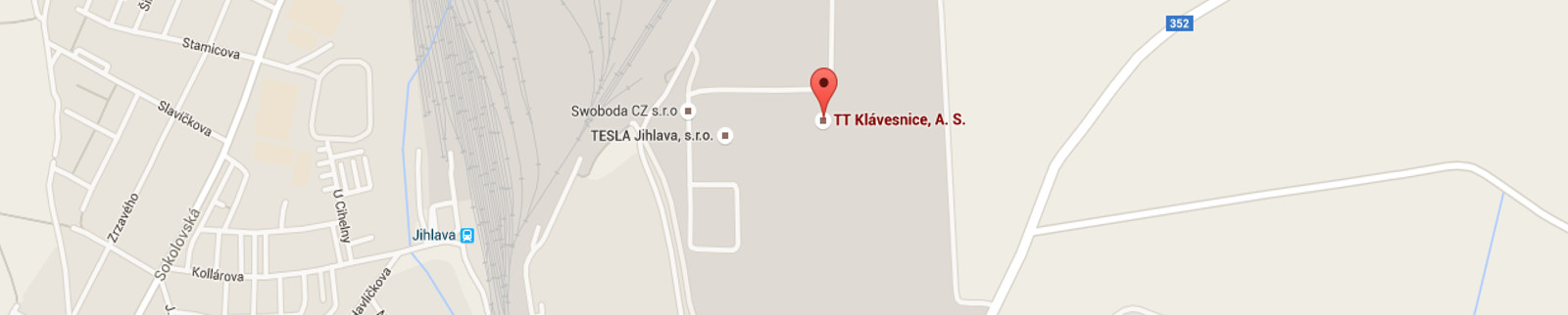
KONTAKT
TT Klávesnice, a.s.
Hruškové Dvory 59
586 01 Jihlava
Česká republika
Průmyslová zóna II
Areál firmy Tesla Jihlava
tel.: +420 567 113 522
GPS
49° 24' 58.15" N
15° 36' 28.58" E