Membrane switches principle
Membrane switches consist of layers of film laminated into a sandwich. Individual layers serve as a carrier (a bottom circuit), springy elements (a top circuit, graphic overlay), and as spacers. Figure 1 shows a design principle of a key
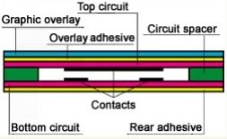
The circuitry and contacts are screen-printed on the films with silver ink (a conductive suspension of finely milled silver particles in a polymer resin). Contacts are made on opposite surfaces of the circuit layers in key areas, where the circuit is to be closed. The circuit films are separated with a spacer with through-cut holes in contact areas, so contacts can contact each other when depressed (see Fig. 2).

Tactile response
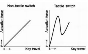
Tactile response is a positive snap-action, signalling that the contacts have contacted each other when you depress a key. The membrane switches are of two sorts: with a tactile feedback, or without it. The outstanding feature of the non-tactile switches is a linear force-travel curve; tactile switches have the distinction of a non-linear curve with a sudden drop in the actuation force (see Fig. 3).
Tactile response can be achieved through polyester domes formed in the graphic overlay layer, or the use of metal domes embedded in the membrane switch.
Materials used for membrane switch production
To assure the high quality of our switches we use top-quality materials which we have selected on the basis of test results. Our customer can choose the material of the graphic overlay according to requirements for the switch's appearance, and the environment in which the switch will be used.
Graphic overlay materials
On principle, the membrane switches are manufactured of the following clear films. To protect a print from scratching or damage, all colours are silk-printed to the non-exposed side of the graphic overlays. The exposed side is printed only with accessory inks (a texture, gloss coating, hardcoat).
| Polyester films | Polykarbonate films | |
|
|
|
|
|
|
|
|
|
|
Polycarbonate films are not suitable for tactile switches or embossing.
Pineout, tail design and conneciton
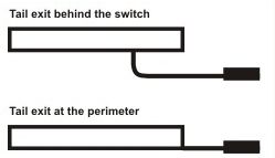
Pinout of a membrane switch can be designed in an X-Y matrix, with a common bus, or as a combination. Contacts of the individual keys are connected to conductive paths on a circuit film. The paths are brought together to one place on the membrane switch, and they exit the membrane switch with a flexible extension of the circuit film, called a tail. The flex-tail can either exit from the perimeter of the membrane switch, or at the back. The membrane switch is then splash-proof (see Fig 4).
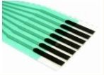
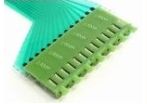
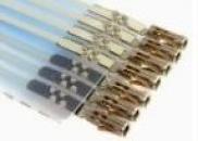
Options of the flex-tail termination:
- Pads for ZIF connector. Suitable ZIF connectors are manufactured and supplied by Molex, AMP (Tyco) or Berg.
- Crimped pins (male contacts), 2.54 mm centreline. Mate IO sockets (not precision ones).
- Crimped sockets (female contacts) with a housing (2.54 mm centreline). Accommodate AMP (Tyco) headers.
Conductive paths on the flex-tail are insulated either by insulation ink or by a dielectric protective film. On request, the flex-tail can be made stiff. Minimum bend radius is 4 mm; when creased sharply, the paths will likely be damaged.
Examples of the flex-tail termination
KONTAKT
TT Klávesnice, a.s.
Hruškové Dvory 59
586 01 Jihlava
Česká republika
Průmyslová zóna II
Areál firmy Tesla Jihlava
tel.: +420 567 113 522
GPS
49° 24' 58.15" N
15° 36' 28.58" E